Friday, August 29, 2008

What Is Delime Cycle Insinger


Vertical scanning circuit is responsible for making the electron beam moves vertically, ie from top to bottom the screen.
So who should be to circulate a current through the windings which form the vertical section of the yoke so that its magnetic field influence on the electron beam onto the screen, or electron beams in the case of a color display .
is of vital importance as this circuit is who we draw the 525 horizontal lines in association with the Horizontal circuit, these lines should have the same spacing between lines (Vertical Linearity) to reproduce the image without distortion, so the current flowing through the Vertical Yoke must have a special feature.
This signal is generated or created a circuit called Vertical Oscillator, but before we know how to create first focus on the part that handles the power, which is one that most fails.
The vertical output stage used in TV but not so new is that which contains two power transistors usually working in Case 375 Push-Pull assembly which means that when one drives the other off and that is achieved two simultaneous signals generated in the vertical oscillations.


In this circuit we have two transistors Q501 and Q502 identified as. Q501 is in charge of "Load", the C520 from the current through the Vertical Yoke, when the C520 starts its charge creates a magnetic field that makes the Yugo s is located at the top of the screen.
As the C520 is loaded, its current decreases as well as its magnetic field and that is where the beam goes down over time looking for the center or point of rest. Past
certain time and when the beam is at the center of the screen horizontally, the signal generated by the oscillator and vertical Driver makes the Q501 was initially driving or active, quit and turn on Q502.
In conducting the Q502 (remember that the electronic structure is such that when the drives Q501 Q502 is cut and vice versa) Q501 stops charging the C520, but when driving the C520 Q502 begins to discharge. This implies that the current in the Yugo changes direction, so the magnetic field also changes and that makes the beam is going from center to the bottom of the screen. This will complete the "fill" the screen.

As you know one you see the beam reached the bottom of the screen, this should rise to the top left of the screen.
It does so by suspending in a "sudden" or unintended current that is flowing through the yoke.
This is achieved when Q502 suspended the "download" total of C520. We know that when you stop electricity flow in a winding natural reaction is that this auto generated a voltage spike, the peak generated in the Yugo is responsible for raising the beam at the top of the screen and the same instant the Q501 has already begun to "load" again the C520, beginning a new cycle of work, repeated 59.94 Hz
These signals we have in the following figure helps us understand what we have explained. Notice how the waveform is such that half cycle influences the Q502 ("ON" or driving) while the Q501 is "off" or off. The other remaining half cycle is responsible for reversing the operation of transistors.

Thursday, August 21, 2008

How To Make A Wahoo Game Pattern


A VGA connector as it is commonly known (other names include RGB connector, D-sub 15, mini sub D15 and mini D15), three-row 15 pin DE-15. There are four versions: original, DDC2, the older and less flexible DE-9, and a Mini-VGA used for laptops. The common 15-pin connector found on most video cards, computer monitors and other devices, is almost universally called "HD-15." HD is "high density", which distinguishes it from the connectors that have the same form factor, but only 2 rows of pins. However, this connector is often mistakenly called DB-15 or HDB-15. VGA connectors and associated cabling are almost always used solely to carry analog component RGBHV (red - green - blue - horizontal sync - vertical sync) video signals along with DDC2 digital clock and data. If the size is a limitation (such as laptops) a mini-VGA port can sometimes be found in place of the full-sized VGA connector.


Tuesday, August 12, 2008

Is Pernicious Anemia Heriditary?

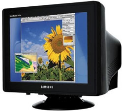
VGA CRT CONNECTOR

The monitor or computer screen, but it is also commonly called "screen" is an output device through an interface, shows the results of processing.


types of monitors


We can find several types of monitors:
• CRT (Cathode Ray Tube or Cathode Ray Tube): consists of a cathode ray tube similar to those of a television
• LCD (Liquid Crystal Display, or LCD displays) used in most digital watches, calculators and the first laptops. They have as much contrast as CRTs.
• TFT (Thin Film Transistor, or Thin Film Transistor): offer higher performance in terms of color, contrast, viewing angle and response time than LCDs.


Operation

CRT: The cathode ray tube (CRT) emits an electron beam that bombards the phosphor coating lining the interior surface of the screen, standing on each pixel (graphic) so that they shine.
The beam makes a horizontal and vertical sweep, causing a trail of light of varying intensity modulated by the numerical data interpreted from the computer.
The color monitor, the CRT emits three electron beams, red green and blue RGB], impinging on each pixel of the screen to compose the image chromatic variables,


Benefits screens
CRT :
play allow a greater variety of colors.
Different resolutions can be adjusted to monitor.
In the opening screen monitors no vertical moire. Disadvantages
screens
CRT :
occupy more space (the more thoroughly the better geometry).
Older models have a curved screen.
Electric fields affect the monitor (the image vibrates).
To enjoy a good image adjustments required by the user.
In the opening screen monitors can be seen several power lines very fine and difficult to see across the screen horizontally, you can see white background.

Technical data, comparing himself:
In the CRT, the refresh rate is the one with the motherboard, the LCD is not always that you can send
CRTs be progressive and interlaced mode, the LCD has a different method of representation. In the CRT
lost about 1 inch size, used for fastening the tube, the CRT is pretty much occupied by the LCD.
The weight of an LCD is increased by the stand for stability, but the monitor itself weighs practically nothing.
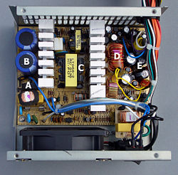
LCDs usually require a transformer external monitor, the CRT goes all the electronics inside the monitor. In the LCD
consumption is lower, and the tension of use by the electronics as well.
In the CRT can be problems of "burn" the phosphor screen, this happens when you leave a still image for long, as the word "insert coin" in the recreation in the LCD problems may be defective pixels ( always on or always off), in addition to other damages.
The flashing of both types of screens is due to the low refresh rate, coupled with the persistence of the brightness of the phosphor, and the memory of each pixel on a CRT and LCD, respectively, to mitigate this defect.
With low refresh rate and a big time match persistence, no flashing, but the persistence of phosphorus is low and the drink is low, this problem occurs. Without emabargo this effect can cause fainting or blurred vision, to stay still on one point, the next screen refresh.

monitors Classes
monitors can be classified by: For the number of colors:
Monitor Monochrome (single color) Monitor
polychromatic (color)


For the signal type to display:
1 .- Digital Monitors:

CGA EGA Monochrome

2 .- Analog Monitors:

Fixed frequency multifrequency VGA


Types of monitors for resolution:

TTL: is text only, they are usually green or amber.


CGA: Son de 4 colores máximo o ámbar o verde, son los primeros gráficos con una resolución de 200x400 hasta 400x600.


EGA: Monitores a colores 16 máximo o tonos de gris, con resoluciones de 400x600,

600x800.


VGA: Monitores a colores de 32 bits de color verdadero o en tono de gris, soporta

600x800, 800x120


SVGA: Super VGA Known as q increases the resolution and the number of colors from 32 to 64 bit true color, 600x400 to 1600x1800.


UVGA: not vary much from Super VGA, only increases the resolution to 1800x1200.


XGA: are high-resolution monitors, special design, graphics capability is very good. In addition the number of colors is larger.


DIGITAL: These monitors receive data through a 9-pin connector. Each pin drives a different kind of signal. Signs include red, green and blue, red side, green secondary, secondary blue, horizontal sync, vertical and tierra.Las signals are transmitted in two states on and off. Digital monitors standard barrel has 3 electron guns in the front of the screen. These guns are called red, green and blue and emit electrons on pantalla.Cada gun shoots only at points of a particular gun. Each gun responds to signals sent to one or two pin monitor connector jack. When a signal is transmitted to pin red, red cannon shoots the red phosphor screen and the spot ilumina.La intensity of light emitted by the phosphor, is interpreted by the human eye and brain, is directly proportional to the number electron impact on rojo.Cuando point the monitor is turned on each point is in one of three states: On, off or on intense. These monitors display a fixed number of colors. The standard signal takes off a voltage from 0 to 0.8v. The signal carried on a voltage of 0.8 to 3.5V voltages are dependent on the particular monitor. The largest number These color monitors that can display are 64. This is imposed by the design of the monitor, not the monitor adapter.

ANALOG: These monitors receive data through a 15-pin connector. Each pin carries different signals. Signs include red, green, blue monitor signals zero, one and two, horizontal sync, vertical and earth.

Parameters screen


Pixel: Smallest unit representable on a monitor. Dot
or (dot pitch): The point size is the space between the colored phosphors of a pixel. Is a parameter that measures the sharpness of the image, measuring the distance between two dots of the same color, it is essential to large resolutions. The smaller spot sizes produce smoother images. A monitor of 14 inches
usually has a dot pitch of 0.28 mm or less. Sometimes it is different in vertical than horizontal, or is an average value, depending on the particular arrangement of colored dots on the screen, and the type of grid used to direct beams of electrons. In LCD and CRT grille opening is the horizontal distance, while the shadow-mask CRT, it is nearly diagonal. The minimum requirement now is to be of 0.28 mm. For CAD
or on the design, ideally of 0.25 mm or less. 0.21 in shadow mask is the equivalent of 0.24 in opening grid.
Useful area: The screen size does not match the actual area used to represent the data.
Max Resolution: is the highest resolution or native (and only) in the case of the LCD which is capable of representing the monitor is related to the size of the screen and point size
Screen Size: is the diagonal distance of a vertex opposite the screen, which can be different from the visible area.
Bandwidth: maximum frequency is able to support the monitor or
Hz vertical refresh rate: are 2 values \u200b\u200bbetween which the monitor can display images on the screen steady.
Hz and horizontal refresh rate: similar to above but horizontally, to draw each line of the screen.
Armor: A monitor may or may not be shielded against external electrical interference and be more or less sensitive to them, so if you are blind or semiblindado take the back cover virtually all the metal in an iron tube contant with earth or ground.
Monitor Type: CRT in there may be 2 types of open grille or shadow mask.
Power Lines: are horizontal lines, which have the opening screen monitors to keep the lines that show the colors perfectly aligned, in 19 "usual usually 2, but there are also 3 lines, some small monitors even have one.


Resolutions:

resolution screen is called the number of pixels that can be located in a particular screen mode. These pixels are in turn divided by the total horizontal and the vertical.
All monitors can work with multiple modes, but depending on monitor size, some of us will be more useful than others:
In general we recommend the following:

Wednesday, August 6, 2008

Can You Get Period Painswhen Your Pregnant


Source Types

When we opened the cabinet of the PC, we can find two types of sources: AT or ATX (AT eXtended).

AT The source has three types of output connectors. The first type, of which there are two, are fueling the motherboard. The other two types, of which there is a variable quantity, feed the peripherals is plugged into a motherboard slotde, such as hard drives, units CD-ROM, floppy, etc.La motherboard connection is via two 6-pin connectors each of which must be plugged so that the two black wires are attached in the center.


The ATX is very similar to the AT, but has a number of differences, both in performance and in voltages delivered to the motherboard. ATX source actually consists of two parts: a primary source, which corresponds to the old AT power (with some additions), and an assistant.


FEATURES

AT power supplies were used until it appeared the Pentium MMX is at the time when would begin to use ATX power supplies.
features of AT sources, is that your motherboard connectors vary from those used in ATX sources, and are more dangerous, since the power is activated through a switch, and in that switch is a voltage of 220V, with risk that would manipulate the PC.

The AT are somewhat rudimentary electronically speaking, when compared with ATXLa technologically ATX, always active, even when the computer is not running, is always powered by a small strain in a state of espera.Las ATX sources have a button connected to the motherboard, and this is responsible for turning on the source, this allows us to make connections / disconnections software. In Fuentes AT, the problem was that there were two connectors to connect to motherboard thus could lead to confusion and shorts, the solution to this is based on a simple trick, leave the center black cables have two connectors, so there is no possible way wrong.

DIFFERENCES IN SOURCES PC

The main difference in performance is noted in the switch, instead of connecting and disconnecting the power supply 220VAC, as does the source of AT, it sends a signal to the main source, indicating that turns on or off, the assistant is always on and always connected 220VAC power, making possible to make connections / disconnections software.

There are three basic differences between the sources of AT and ATX power
• Has an extra-voltage line, that of +3.3 v
· The ATX power supplies have only a 20-way connector • Has
wire "power on", the source is turned off by software


ATX CONNECTOR


CONNECTOR AT


ADVANTAGES AND DISADVANTAGES


One advantage is that the sources ATX does not have a switch that turns on / off source, if it is a button connected to the motherboard, and this is responsible for turning on the source, this means for the power connections / disconnections software.


PRICES

Power Supply
Power Supply 350 W ATX P4 24 Pin

$ 178.60

ATX Power Supply 450 W 24 Pin P4 box

$ 227.46 Power Supply 630 W ATX P4 24 Pin, 2 fans, 2 S-ATA connector


$ 306.65


Nadine Jansen In A Bra

PC SOURCES SOURCES AND LINEAR SWITCHING DIODES

Switching power supply

A switching power supply is an electronic device that converts electrical energy by switching transistors. While a voltage regulator uses transistors biased in the active region of amplification, switching power supplies use the same switch turns at high frequency (100-500 KHz typically) from cut (open) and saturation (Closed). The resulting square waveform is applied to the ferrite core transformers (The iron cores are not suitable for these high frequencies) for one or more output voltages of alternating current (AC) which are then ground (with fast diode) and filtered (inductors and capacitors) for the DC voltajesdesalida (CC).


A - bridge rectifier


B - Input Capacitor


C - Transformer


D - output filter coil


E - output filter capacitors


OPERATION


Rectifier: converts AC continuously. Llaveador: Under orders from the pulse generator, leads or blocks, at high frequency. Filter: decreases (almost eliminating) the AC at the output, leaving it entirely continuous. Compare: Take a sample of the output, and compares with a reference. Generates an error signal that goes to the pulse generator. Pulse Generator: Generate pulses llaveador go to, to be proportional to the error voltage available at its input.
The AC signal is rectified and converted into pulses continuously. These pulses are delivered to a llaveador, leading, or block, high frequency (typically more than 10,000 Hz.)
The key output is filtered by a normal capacitive. Since switching (llaveamiento) is in high frequency filtering is easy.
A sample of the output voltage. This is applied to a comparator, whose second input has a reference voltage. The comparator takes an error signal that is proportional to the difference between the output and the reference. This error signal is sent to the pulse generator so that it orders the leading Llaveador more or drive less, as needed.


Power Comparison between switched and linear
There are two main types of regulated power supplies available: Switched and linear. The reasons for choosing one type or another can be summarized as follows.
Size and weight - linear power supplies use a transformer operating at a frequency of 50 or 60 Hz. This low frequency transformer is several times larger and heavier than a corresponding transformer switching power supply, which typically operates at frequencies from 50 kHz to 1 megaciclo.La design trend is to use increasingly higher frequencies while the transistors allow to reduce the size of passive components (capacitors, inductors GCA).
Output Voltage - linear power supplies regulate the output using a higher voltage in the previous stages and then dissipating energy as heat to produce a lower voltage, regulated. This voltage drop is necessary and can not be eliminated by improving the design. The switching power supplies can produce output voltages that are lower than the input voltage, the higher the voltage and even reverse the input voltage, making them more versatile and adaptable to varying input voltages.
Efficiency, heat, and power dissipation - A linear regulated supply voltage or leakage current dissipating excess energy as heat, which is inefficient. A switching power supply control signal used to vary the pulse width, taking food only the power required by the load. In all SMPS topologies, turn off and turn on the transistors completely. So, ideally, switching power supplies are 100% efficient. The only heat generated is given by the non-ideal characteristics of components. Losses in switching transistors, direct resistance of saturated transistors, equivalent series resistance in the inductor and capacitors, and voltage drop down the rectifier efficiency. However, optimizing the design, the amount of energy and heat dissipation can be minimized. A good design can have a conversion efficiency of 95%. Typically 75-85% in sources between 10-50W.Las more SMPS efficient use synchronous rectification MOSFET transistor saturated at the right time instead of diodes.
Complexity - a linear regulator is ultimately a power transistor, a voltage regulator IC and a noise filter capacitor. But a typically contains a switching power supply controller IC, one or more power transistors and diodes as well as transformers, inductors, and filter capacitors. Multiple voltages can be generated from the same transformer core. It uses the pulse width control input but different outputs can be difficult for load regulation. Both need a careful selection of processors. In switching power supplies due to operation at high frequencies the losses in the tracks of printed circuit inductance and stray capacitance loss become important. Radio Frequency Interference
- The current in the switching power is abrupt, and contains a large proportion of high-frequency spectral components. Long cables or tracks between components can reduce the effectiveness of high frequency filters capacitors at the input and output. This high frequency current can generate unwanted electromagnetic interference. EMI filters and RF shielding are needed to reduce interference. Sources Linear power generally do not produce interference, and are used to provide power where radio interference should not occur.
electronic noise in the output terminals of inexpensive linear power supplies with poor regulation may experience a small AC voltage "mounted" on the CC. twice the supply frequency (100/120 cycles). This "ripple" (Ripple in English) is generally in the order of several millivolts, and can be suppressed with larger filter capacitors or better voltage regulators. Small AC voltage that can cause problems or interference in some circuits, such as cameras similar photographic fed up with this kind of sources may have unwanted brightness modulation and distortion in the audible hum sound. The linear power quality better ripple deleted. Instead of switching power supplies typically exhibit no ripple in the frequency of feeding, but generally more noisy output at high frequencies. Noise is generally related to switching frequency.
Acoustic Noise - linear power supplies typically emit a faint ringing in the low frequency power, but this is rarely audible (vibration coil and transformer core plates are usually the cause). Sources switched with much higher operating frequency, are generally not audible to humans (unless they have a fan, as in most personal computers). Malfunction of the switching power supplies can generate high-pitched sounds, generating acoustic noise in the oscillator frequency. Power Factor
linear supplies are low power factor because the energy is obtained from voltage spikes alimentación.La line current in the simple switching power supplies do not follow the voltage waveform, but in a manner similar to Linear energy sources is obtained only from the highest part of the sine wave, so its use more and more common in personal computers and fluorescent lamps constituted an increasing problem for the distribution of energía.Existen SMPS with a pre-correction power factor which greatly reduces this problem and are compulsory in some European countries particularly from certain powers.
electrical noise on the main feed line may receive electronic switching noise may cause interference with teams of A / V connected to the same phase. The linear power rarely have this effect. The SMPS well designed with filters to minimize input interference in the main power line.

Tuesday, August 5, 2008

Is Ringworm Contagious Wh


Welding is a molten metal joining two pieces of metal, in the same way that performs the operation of melting an alloy to join two metals but different from when two pieces of metal welded to join together to form a welded joint. The
industry of electronic The alloy of tin and lead is most often used, but other alloys , this combination gives the best results. The mixture of these two elements creates an uncommon event. Each element has a high melting point, but when mixed produce an alloy with a lower melting point than any of the items for this we must learn the basics for welding. Without this knowledge
is difficult to envision that occurs when making a solder joint and the effects of the different parts of the process.


Welding Theory

Before making a union, it is necessary that the solder "wet" base metals or base metals to form the union. This is the most important factor when welding. When welding intermolecular bond is formed between the solder and metal. Welding molecules penetrate the structure base metal to form a solid extructura, totalmemte metal.


are commonly used in electronic power welders reduced, since generally it is delicate work. In plumbing, however, are used to weld pipe welders more power and lamps, and other welding systems.
It is a tool that has enormous scope, either for new assemblies or for repair. The welder must allow soldering operations for the union of two or more drivers, or drivers with items of equipment. Due to their frequent use, the welder must produce, among other features, great reliability and durability.
In general, it is a mass of copper (tip), which is heated indirectly by an electric heater connected to an electrical outlet (usually 220v outlet). The types that are usually found in the market can be classified into common welding or "pen" and soldering gun.

Types of welders

This is the classic type welder pencil 30w. Its warming is permanent and has a high thermal inertia. Both at the time of the weld and in the pauses of this work, the welder stays connected to the mains. It is appropriate for repetitive and numerous.


The soldering gun. The tip is heated by the effect of a large current through it (the bulky handle carries in a transformer that produces it). Useful for odd jobs and instantly warming. Not widely used in electronics because the tip is often not fine enough and accurate.


Media Types

Since the welder keeps the tip hot (about 250 ~ 300 º C), it is necessary to use a support which leave for time is not used, to avoid burning the work table. Here are some examples:


1. Support typical for light-duty welders. It has sponge.
2. JBC support that allows you to place the iron in two different ways. Has
sponge.
3. Support easier. Can constructed with a piece of sheet metal and a wooden table
.
4. Welder with all the points that can be fitted: fine point tip
thick, puna desoldering integrated circuits and even accessory